Remote IO Control Circuit
Rich Lewis KE5HHU © 2007
Since I acquired several of these RELCOMM 4 port relays with the 9 pin TTL control connector I decided to use these for IF switches for my array of Transverters up on the rooftop. The relay is good up to 4 GHz at 100W, uh maybe. I'll be switching 144 MHz IF at a few milliwatts and a 222 antenna fed about 5W. I also put the ability to turn off and on 4 10 amp DC relays and to monitor their output voltage to verify fuse and relay integrity. This data can then be periodically fed back to the Host Control Circuit though the use of a serial communications path. In this case the PIC16F88 was chosen because of its additional A/D converter.
Relay Driver Circuit
In order to provide additional drive current to the +12V DC relays I use a series of NPN transistors. I found these aren't necessary since the 16F88 chip is able to drive the relays directly.
Remote Selector Circuit
This board holds the DC relays and fuse holders.
Host Control Program
Here is a screen shot of the Host Control Program. It was written in Visual Basic using Visual Studio 2005.
The green buttons show the DC relay is engaged and the voltage reading at the fuse.
The radio button series selects the IF / Antenna relay.
Each of the labels can be customized by clicking and editing.
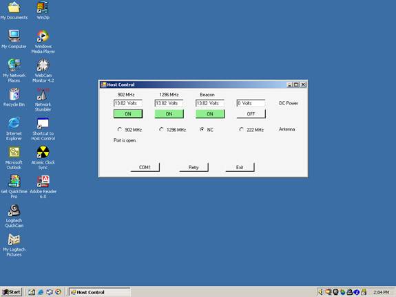
The accuracy of the voltage measurement in this circuit is 10mV. The future circuits will have a 30 Volt range and an accuracy of about 30mV.
Communications between the Host and Remote uses a custom command sequence from the Host to program and interrogate the Remote to send status and voltage or temperature measurements using a modified uuencode scheme. The A/D converter at the Remote is 10 bit.